A Fenwick tree is a binary tree used to efficiently handle cumulative frequencies or sums in an array.
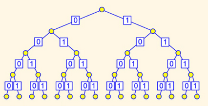
Without loss of generality we shall examine a 16-element array. Imagine a binary tree imposed on top of the array. Furthermore, label all the left edges in this tree with a "0" and all the right edges with a "1". We get something like this:

This is the so called Fenwick tree (or binary indexed tree). As can be seen, all the leaf nodes are indexed by a 4-digit binary number from 0000 till 1111 (left to right). Don't worry about this indexing for the time being. Now suppose that every leaf node contains the numeric value of its mapped array element and that every non-leaf node contains the sum of its two children. This means that the root node of the tree will contain the sum of the whole array. Also the left(right) child of the root will contain the sum of the left(right) half of the array and so on and so forth.
Up till this point we haven't really done anything special apart from storing partial sums. What we really want to do is to use these partial sums to compute cumulative sums in the array. We can do this for example by carefully selecting some nodes and returning their sum. This poses the question: Is there a strategic way to mark some nodes of the index tree that allows efficient cumulative sum calculations? It turns out that there is and this is the main idea behind Fenwick trees.
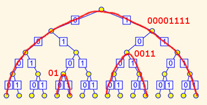
Before describing this marking, we first elaborate on the concept of uniform arcs. A uniform arc in a binary indexed tree is a directed path from any leaf to any other leaf situated to its left such that the labels on this path have the form: "00...011...1" (read from left to right). We can also assume the existence of a uniform arc from every leaf node to itself (with a length of 0). For example, the uniform arc connecting the fourth leaf to the first has a label of "0011". See the following figure for some illustrative examples of uniform arcs.

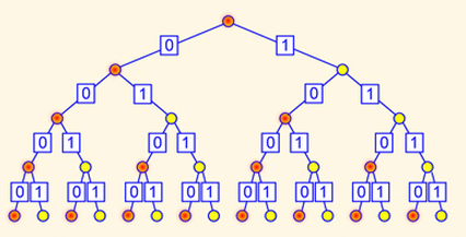
Now comes the crucial idea of Fenwick trees. The marking that allows us efficient computation of cumulative sums is obtained by coloring the middle node of the largest uniform arc emanating from every leaf node. This marking is illustrated in the following figure:

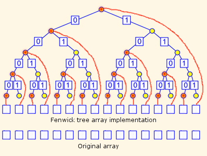
The nodes coloured in red are the so called responsibility nodes. This is due to the fact that each red node is responsible for maintaining the sum of values of all leaf nodes beneath it. Note that there are 16 responsible nodes and the whole tree can be implemented using a single array of the same size of the original array and here is when the binary indexing becomes handy. The yellow nodes are not needed and are used here only for pedagogical purposes. Note that all non-leaf responsible nodes have indexes length < 4 bits. We can restore the 4 bit length by padding successive "1"s to the right of the corresponding index. After applying the padding, the indexes of all responsible nodes fit nicely into a single array. See the following figure:

All we have to do now is figure out a way to compute (or update) the cumulative sum for every leaf node as follows:
A- To read the cumulative sum at a leaf, we first prepend a "0" and append a "1" to its index then we use the "flipping" technique as follows. Starting from the right most bit we first note the first "1" to "0" transition then flip all "1"s to "0"s one at a time. The sum of the found responsible nodes is then returned. The following examples illustrate this technique: (note: node "" is the root)
leaf "1010", becomes "010101" => responsible nodes: {"1010", "100", "0"}
leaf "1011", becomes "010111" => responsible nodes: {"10", "0"}
leaf "0111", becomes "001111" => responsible nodes: {"0"}
leaf "1111", becomes "011111" => responsible nodes: {""}
B- To update a value, trace all responsible nodes from the leaf to the root and update them accordingly. The tracing is done by prepending and appending a "0" to the index of the leaf and then successively noting all "0" to "0" and "1" to "0" transitions in the resulting index starting from rightmost bit. The following examples illustrate this technique: (note: node "" is the root)
leaf "1000", becomes "010000" => responsible nodes: {"1000", "100", "10", ""}
leaf "1111", becomes "011110" => responsible nodes: {""}
leaf "0100", becomes "001000" => responsible nodes: {"0100", "010", "0", ""}
leaf "0000", becomes "000000" => responsible nodes: {"0000", "000", "00", "0", ""}
You can verify the above examples by direct visual inspection of the third figure. A detailed explanation of Fenwick trees can be found at BIT: What is the intuition behind a binary indexed tree and how was it thought about? and https://www.topcoder.com/community/data-science/data-science-tutorials/binary-indexed-trees/. Hopefully by now reading the mentioned sources will be much easier.


