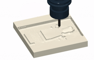
For a CAM (Computer Aided Manufacturing) software, and more specifically, for the simulation of the subtractive manufacturing, I would like to understand how to design the representation.
In subtractive manufacturing (e.g. a Mill), a piece of raw material like a cube or a cylinder is machined. That is, a milling bit (like the bit of a drill) is moved following a path (defined by a GCode program), which slowly remove material from the raw part until the desired piece is formed. Subtractive manufacturing is the reverse process than 3D printers, where material is deposited following a GCode program path.
By representation, I refer to that beige raw piece in the image: how to efficiently represent it in memory, but more important, how to efficiently calculate it new shape, every few milliseconds, based on the path and shape of the tool bit.
Notes: This is not about 3D APIs, I have experience with OpenGL/Vulkan, but about how to calculate the shape modification.
My first understanding of the problem is that each few milliseconds ∆t, I could calculate the parallelepiped produced by the linear motion of the tool/bit from an origin (where the tool/bit is at t) to a destination (where the tool is at t+∆t). And perform a 3D boolean subtract of the raw piece with it.
Note: This is for an end-mill, for a ball-mill (with rounded end of the tool bit) the parallelepiped become a more complex shape.
However, I am not sure that a 3D boolean operation can be performed real-time.
I got suggested to divide the raw piece into small "voxels" where each voxel represent a configurable cubic space (e.g. 1mm^3). This with the intend to simplify the boolean operation.
Is there a common approach to this problem?
Ideas of algorithms would help, but I am more interested in some demonstrated solution: either a solution known to be implemented in some of the major CAM software, or a solution demonstrated to be effective by some research paper.

