0
$\begingroup$

I would like to draw an arc from a specific point to a goal point, during the process of drawing a larger path. I would like to do it using bezier curves, which aren't adequate for modeling circular arcs, but these equations found here seem to potentially estimate the arc pretty well (I can't tell if these equations correctly implement the circular arc using cubic Bezier curves (yet), but it seems like a good start). Here is the equations from that link.

start coordinate = {
  x: R,
  y: 0
}

control point 1 = {
  x: R,
  y: R * 4/3 * tan( phi / 4)
}

control point 2 = {
  x: R * ( cos(phi) + 4/3 * tan( phi/4 ) * sin(phi) ),
  y: R * ( sin(phi) - 4/3 * tan( phi/4 ) * cos(phi) ),
}

end coordinate = {
  x: R * cos(phi),
  y: R * sin(phi)
}

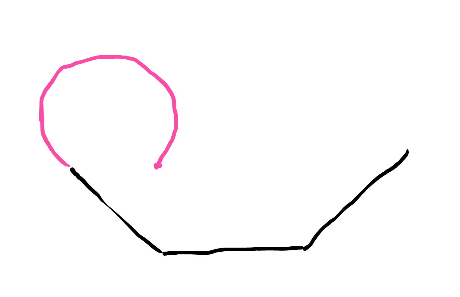
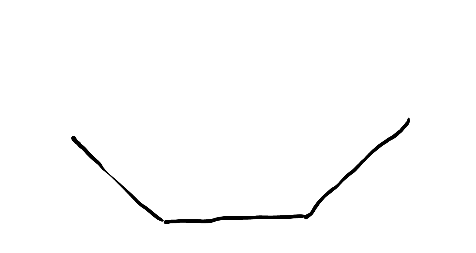
So let's say I start with a drawing of a path composed of some stuff, in this case just a few connected line segments (doesn't matter what they are):

enter image description here

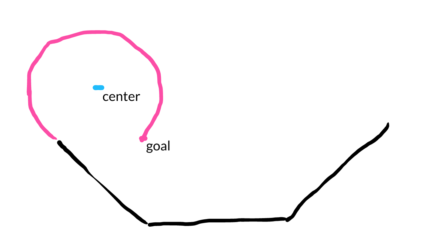
Then what we want to do next, from the current point we left off at, is draw an arc. This is what that arc might look like:

enter image description here

You can see that there is a center where we can draw a radius, and a goal point where the arc ends (so it doesn't complete a whole circle).

enter image description here

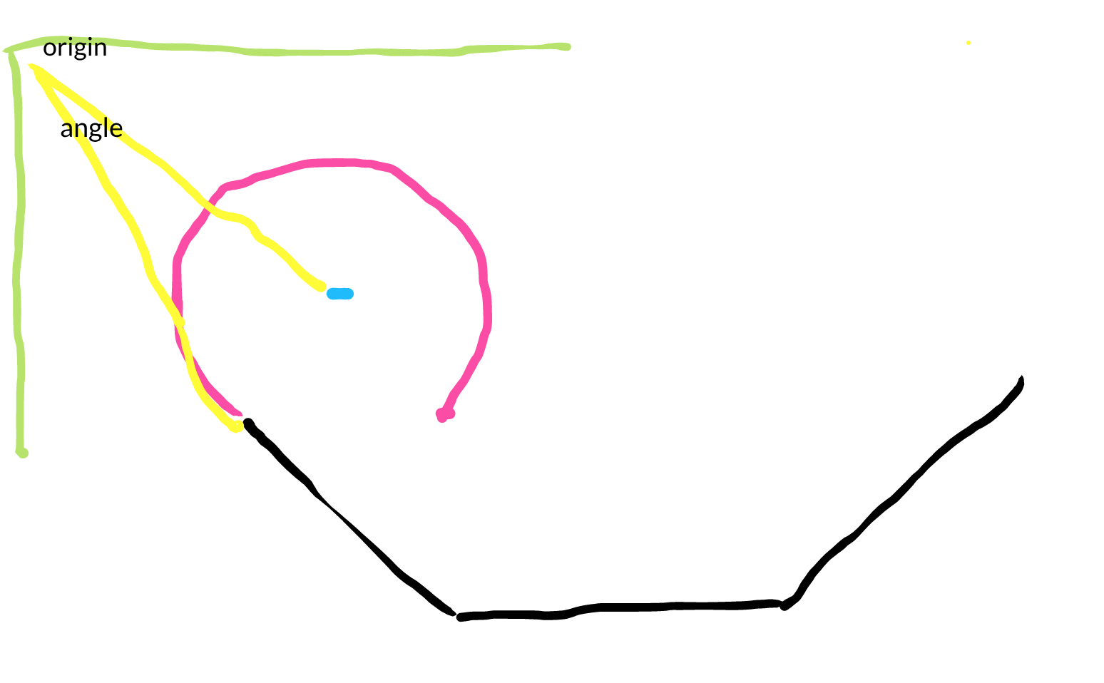
My question is, how to determine the angle phi (in the equation above). That way I can use the equation. I am not sure what my current orientation is, if it is all relative to a global coordinate space or what. This is for traditional graphics. So need to figure that part out. Let's say it is a global coordinate space and not relative to the direction I moved along the path. Then this would be the angle:

enter image description here

I don't know, I'm already confused. So somehow I need to figure out some angle, which I'm not sure what to do. From there I think I could figure out the rest. Any help would be appreciated.

After the radius is found, then these equations above would take my simple circular arc, and turn it into a cubic Bezier equation so hopefully it could be drawn in an environment that only supports that and not arcs.

$\endgroup$

1 Answer 1

0
$\begingroup$

I think you have to determine the center C of your circle first. From your drawing, I suppose you want the last black segment to be tangeantial to the circle. Let say this last segment coordinates are P0 (x0, y0) and P1 (x1, y1).

Then the vector is:

vy = y1-y0
vx = x1-x0
with norm vr = sqrt(vy²+vx²)

And the vector vc from P1 to C is (2 choices depending on orientation):

vcy = +R*vx/vr or -R*vx/vr
vcx = -R*vy/vr or +R*vy/vr

then you obtain C coordinates (cx, cy) applying vc to P1. Now, your rotation angle phi must be expressed in the Cxy frame whatever the curve equation you use. The translation from (X, Y) in Cxy to (x, y) in Oxy is:

y = Y+cy
x = X+cx  

Now about Bezier cubic curves, the equations you give assume you are starting at theta0=0 which is not the case on your figure. You can compute the starting angle with arctan2 (implemented on most of languages):

theta0 = arctan(-vcy, -vcx)

Then to plot a large angle arc with Bezier you actually have to cut it in small angle curves (let's say 30° max). So cut the (theta0, theta0+phi) angle into several (a, b) angles. NB: phi is negative on your figure (clockwise).

For every (a, b) angle, your Bezier cubic curve equation in Oxy frame is then:

K= 4/3 * tan( (b-a)/ 4)

start : y = cy+R*sin(a)
        x = cx+R*cos(a)

cp1 : y = cy+R*(sin(a)+K*cos(a))
      x = cx+R*(cos(a)-K*sin(a))

cp2 : y = cy+R*sin(b)- K*cos(b))
      x = cx+R*cos(b)+ K*sin(b))

end : y = cy+R*sin(b)
      x = cx+R*cos(b) 

I did not not check these equations, I hope there is no mistake in.

$\endgroup$

Your Answer

By clicking “Post Your Answer”, you agree to our terms of service and acknowledge you have read our privacy policy.

Not the answer you're looking for? Browse other questions tagged or ask your own question.