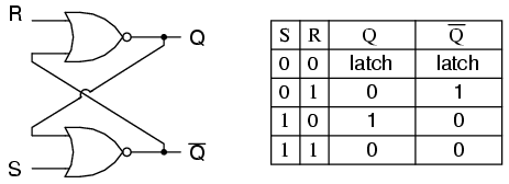
A flip-flop is implemented as a bi-stable multivibrator; therefore, Q and Q' are guaranteed to be the inverse of each other except for when S=1, R=1, which is not allowed. The excitation table for the SR flip-flop is helpful in understanding what occurs when signals are applied to the inputs.
S R  Q(t) Q(t+1)
----------------
0 x   0     0
1 0   0     1
0 1   1     0
x 0   1     1
The outputs Q and Q' will rapidly change states and come to rest at a steady state after signals have been applied to S and R.
Example 1: Q(t) = 0, Q'(t) = 1, S = 0, R = 0.

State 1: Q(t+1 state 1)  = NOT(R OR Q'(t)) = NOT(0 OR 1) = 0
         Q'(t+1 state 1) = NOT(S OR Q(t)) =  NOT(0 OR 0) = 1

State 2: Q(t+1 state 1)  = NOT(R OR Q'(t+1 state 1)) = NOT(0 OR 1) = 0
         Q'(t+1 state 2) = NOT(S OR Q(t+1 state 1))  =  NOT(0 OR 0) = 1

Since the outputs did not change, we have reached a steady state; therefore, Q(t+1) = 0, Q'(t+1) = 1.


Example 2: Q(t) = 0, Q'(t) = 1, S = 0, R = 1

State 1: Q(t+1 state 1)  = NOT(R OR Q'(t)) = NOT(1 OR 1) = 0
         Q'(t+1 state 1) = NOT(S OR Q(t))  = NOT(0 OR 0) = 1


State 2: Q(t+1 state 2)  = NOT(R OR Q'(t+1 state 1)) = NOT(1 OR 1) = 0
         Q'(t+1 state 2) = NOT(S OR Q(t+1 state 1))  =  NOT(0 OR 0) = 1


We have reached a steady state; therefore, Q(t+1) = 0, Q'(t+1) = 1.


Example 3: Q(t) = 0, Q'(t) = 1, S = 1, R = 0

State 1: Q(t+1 state 1)  = NOT(R OR Q'(t)) = NOT(0 OR 1) = 0
         Q'(t+1 state 1) = NOT(S OR Q(t)) =  NOT(1 OR 0) = 0

State 2: Q(t+1 state 2)  = NOT(R OR Q'(t+1 state 1)) = NOT(0 OR 0) = 1
         Q'(t+1 state 2) = NOT(S OR Q(t+1 state 1))  = NOT(1 OR 0) = 0

State 3: Q(t+1 state 3)  = NOT(R OR Q'(t+1 state 2)) = NOT(0 OR 0) = 1
         Q'(t+1 state 3) = NOT(S OR Q(t+1 state 2))  = NOT(1 OR 1) = 0

We have reached a steady state; therefore, Q(t+1) = 1, Q'(t+1) = 0.


Example 4: Q(t) = 1, Q'(t) = 0, S = 1, R = 0

State 1: Q(t+1 state 1)  = NOT(R OR Q'(t)) = NOT(0 OR 0) = 1
         Q'(t+1 state 1) = NOT(S OR Q(t)) =  NOT(1 OR 1) = 0

State 2: Q(t+1 state 2)  = NOT(R OR Q'(t+1 state 1)) = NOT(0 OR 0) = 1
         Q'(t+1 state 2) = NOT(S OR Q(t+1 state 1))  = NOT(1 OR 1) = 0

We have reached a steady state; therefore, Q(t+1) = 1, Q'(t+1) = 0.


Example 5: Q(t) = 1, Q'(t) = 0, S = 0, R = 0

State 1: Q(t+1 state 1)  = NOT(R OR Q'(t)) = NOT(0 OR 0) = 1
         Q'(t+1 state 1) = NOT(S OR Q(t)) =  NOT(0 OR 1) = 0

State 2: Q(t+1 state 2)  = NOT(R OR Q'(t+1 state 1)) = NOT(0 OR 0) = 1
         Q'(t+1 state 2) = NOT(S OR Q(t+1 state 1))  = NOT(0 OR 1) = 0

We have reached a steady; state therefore, Q(t+1) = 1, Q'(t+1) = 0.


With Q=0, Q'=0, S=0, and R=0, an SR flip-flop will oscillate until one of the inputs is set to 1.

Example 6: Q(t) = 0, Q'(t) = 0, S = 0, R = 0

State 1: Q(t+1 state 1)  = NOT(R OR Q'(t)) = NOT(0 OR 0) = 1
         Q'(t+1 state 1) = NOT(S OR Q(t)) =  NOT(0 OR 0) = 1

State 2: Q(t+1 state 2)  = NOT(R OR Q'(t+1 state 1)) = NOT(0 OR 1) = 0
         Q'(t+1 state 2) = NOT(S OR Q(t+1 state 1))  = NOT(0 OR 1) = 0

State 3: Q(t+1 state 3)  = NOT(R OR Q'(t+1 state 2)) = NOT(0 OR 0) = 1
         Q'(t+1 state 3) = NOT(S OR Q(t+1 state 2)) =  NOT(0 OR 0) = 1

State 4: Q(t+1 state 4)  = NOT(R OR Q'(t+1 state 3)) = NOT(0 OR 1) = 0
         Q'(t+1 state 4) = NOT(S OR Q(t+1 state 3))  = NOT(0 OR 1) = 0


As one can see, a steady state is not possible until one of the inputs is set to 1 (which is usually handled by power-on reset circuitry).

