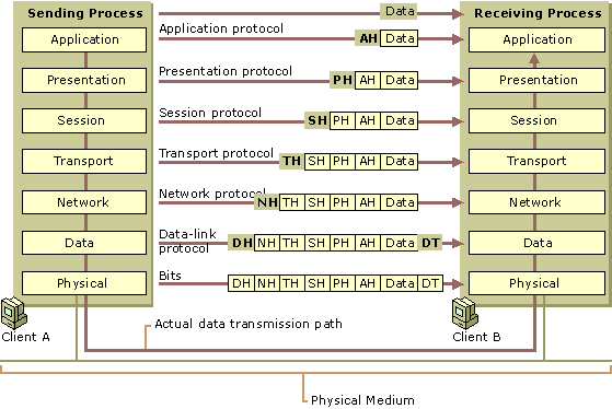
OSI Layer 2 is usually tasked with getting the information from the upper layers, provided in octets (bytes), into bits suitable for sending over the physical link (OSI Layer 1). On the receiving side, the bits need to be converted back into bytes.
Links do not usually have the nice property of sending an exact sequence of 0 and 1. There is timing to consider (e.g. on a TTL line, scan the voltage n times per second). shifting (especially in parallel lines), bit damage, etc. Also, on asynchronous lines (most ones, except ATM (asynchronous transfer mode), textbook example for a synchronous protocol, always makes me smile), there are periods of no data transfer. This means that the sender and recipient somehow have to signal beginning and end of “transfer blocks”.
This is all rather difficult, so the frame header and trailer do not necessarily have to be full numbers of 8-bit blocks. They often include some easily-recognised bit patterns, such as a large-ish number of either all-zeroes or all-ones, followed by a toggle sequence such as 010101, and only then followed by data; this allows the recipient to synchronise on the sender better. Even DCF77 works like that, so receivers can synchronise to the exact beginning of a minute.
Going further, Layer 2 switches often operate in “fast pass-through mode”, in which they only need to have received the header (containing the target (and often source) address) to decide where to send the frame, not needing to fully buffer the entire frame for this decision, leading to faster throughput (less latency). On the other hand, the sending side may, indeed, wish to calculate the checksum on the fly and append it, in the trailer, which is only needed on the recipient side, not on the switches in between. This all allows for cost reduction in hardware.

