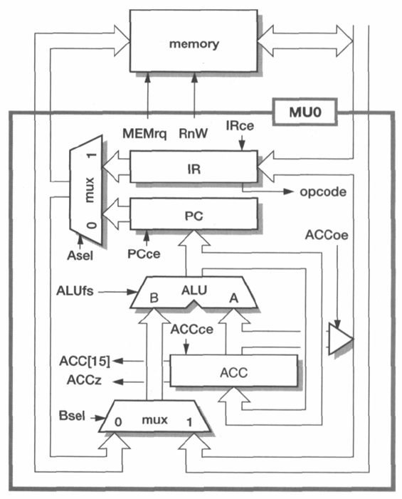
I've been studying about CPU and I am trying to implement a small CPU, like MU0.
Control unit gets instruction and generates and gives several control signals to other parts of CPU, such as ALU, PC, ACC, etc. And I know that these works in one clock cycle.
But I have some quetions.
- Meaning of Signals (0 or 1) in Clock Cycle
Each one clock cycle has signal 1 first and has 0 next. Since CPU is an electronic equipment, 1 would mean current is flowing (so, "turn on") and 0 would mean no current flow (so, "turn off").
So, does each control signals connected to the clock cycle circuit turn off when the clock cycle is 0 at the same time, if we ignore delays of the circuit?
If not, i.e., if control signals can be 1 although clock cycle is 0, I can state my hypothesis:
Clock signal is only meaningful and only used when signal toggles 1→0 or 0→1. Control unit can not work when its signal stays in the same value since it can not recognize time is going.
Is that true or false?
- Timing to Control each Control Signals

(source: tistory.com)
Here is the structure of MU0, one of simple CPUs.
If we want to store data from memory with the address in PC to IR and increase PC by 1 (i.e., PC = PC + 1), the manual says that setting control signals as below would do that.
- 0 : Asel, Bsel, ACCce, ACCoe
- 1 : PCce, IRce, MEMrq, RnW
- with ALU function B+1.
Note that the value of PC goes in ALU and the output of ALU is PC+1 since Asel(A selector), Bsel are 1.
But, since PCce(PC chip enabler) is 1, PC change the value by the input of PC, which is the output of ALU.
It seems good to make PC as PC+1. But my questions is:
This is an infinite loop theoritically since PC+1 would goes into ALU and PC+2 would save in PC, and then PC+2 would goes into ALU and PC+3 would save in PC, ... so and on until one clock cycle ends.
To avoid this, controlling timings would be different for each control signals. Is this really true, or is there another solution?
Thanks.
